Closed Loop Regulation of an Innovative Ultrasonic Micro Actuator
- Degree programme: BSc in Mikro- und Medizintechnik
- Author: Oliver Julian Hess
- Thesis advisors: Prof. Dr. Thomas Niederhauser, Fabio Modica
- Experts: Francesco Filotto, Raphaël Hoesli, Benjamin Pruijs
- Industrial partner: Miniswys SA Biel/Bienne
- Year: 2023
Ultrasonic piezo actuators use the reciprocal piezo effect to generate motion. By applying a high-frequency voltage to the piezoelectric element, an ultrasonic vibration is induced that results in mechanical displacement by friction. This work is dedicated to the closed loop position control of a linear ultrasonic actuator developed by Miniswys SA
Background
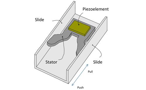
Miniaturization is an ongoing process in technology. It is an effort to minimize the size of components and increase their efficiency without reducing their performance. Particularly motors like the linear ultrasonic actuator (UCM) manufactured by Miniswys SA are increasingly used in modern applications. By resonating the stator in two different resonance frequencies the slide can move linearly in two direction. Whereby one frequency results in a motion in push direction the other will trigger a movement in the pull direction (See Figure 1).
Goals
- Identification and linearization of the system
- Closed loop position control
- Positioning in 50ms and additional 10ms per millimetre of distance travelled, with a position error smaller than 5µm
Methods
A linear model of the UCM has been acquired first. For this purpose, the frequency response of the system was measured and then compared with the transfer function acquired by fitting the step response of the system. Based to this simplified system model, the control algorithms were designed and subsequently simulated and optimized in MATLAB / Simulink. Finally, the controllers were tested and evaluated in a closed loop system.
Result
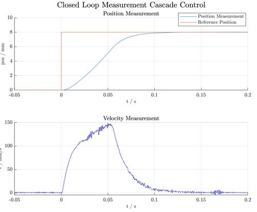
The result of the system identification and linearization revealed an Integrative plant for the position, leading to a PD controller with lowpass in a first attempt. The simulation of an ideal plant showed a low settling time, no steady state error and little to no overshoot. However, when nonlinear factors such as saturation and velocity limitations are included in the simulation model, a steady-state error becomes apparent. This was afterwards confirmed with a closed loop experiment. In a further trial, a cascade controller was implemented (See Figure 2). whereby a PI velocity controller was used in the inner loop and a PD position controller with lowpass filter in the outer loop.
Discussion
A simple PD controller will result in a steady state error due to the nonlinearities of the actuator. The cascade controller was able to compensate for the non-linearities since the inner PI control loop could keep the speed at the desired level.