Development of a System with Controlled Pressure Amplification and Continuous Oil Flow
- Degree programme: BSc in Mikro- und Medizintechnik
- Author: Aviv Marmorosch
- Thesis advisor: Fabio Modica
- Expert: Matthias Kohler
- Industrial partner: Bucher Hydraulics AG Frutigen
- Year: 2025
This thesis aims to develop a continuous pressure amplification system to test hydraulic components requiring pressures above 320 bar. A new setup with three alternately controlled cylinders enables continuous pressure amplification. Based on an analytical model, a suitable control algorithm is simulated and implemented, while a state machine coordinates smooth transitions between cylinders.
Introduction
This thesis develops a hydraulic system for continuous pressure amplification using cylinders. It must operate vibration-free, quietly, and deliver small to medium flow rates at pressures up to 500 bar. The system enables valve testing beyond the central hydraulic supply’s capacity. Specified performance requirements include a settling time below 0.5 s and a steady-state accuracy within ±6 bar.
Methods
Concept, System Modeling and Verification
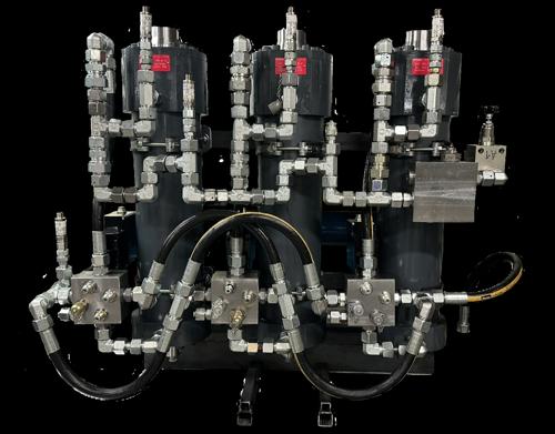
The system consists of three independently controlled cylinders (see Fig. 1) actuated using highly responsive FOSA valves. The dynamic behavior of the series connection of one valve, cylinder, and load is modeled using fluid and classical mechanics. Unknown model parameters are identified using MATLAB’s System Identification Toolbox. The resulting model is verified by comparing simulations with experimental data.
Controller Design and State Machine
Based on the verified model, a discrete PI controller is designed using the EDTE (Exact Time-Discrete Equivalent) method to compensate the system’s dominant pole. The control system for a single cylinder is first simulated in Simulink, then implemented and tested in LabVIEW. In the final application, all three cylinders operate alternately. A state machine governs the transition from an empty to a full cylinder, avoids pressure spikes, and ensures continuous flow.
Results
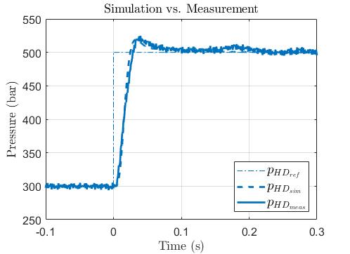
The comparison of the system model with measured step and frequency responses shows a satisfactory overlap and thus verifies the system model. Fig. 2 shows the correlation of the simulated and implemented feedback control system. The controller handover is realized via a controlled ramp and a dynamically adjusted handover point, preventing pressure spikes and losses and ensuring a smooth and continuous output.
Discussion and Outlook
Using the described approach, the specified requirements on transient time and accuracy are met. Current limitations include the use of a constant load during validation and future work should evaluate the controller’s robustness under varying load conditions. Further steps are implementing a clean software interface and integrating the valve logic into a central hydraulic control unit.